What's in the Box - Grillo Pulse
This page describes all components included with your Grillo Pulse sensor.
Package contents
1. Grillo Pulse sensor unit (PCB)
The main sensor board (98.5 x 70mm, 50g) containing:
- 4.5Hz geophone with 32-bit ADC
- Ultra-low noise MEMS triaxial accelerometer with 20-bit ADC
- LTE Cat-4 cellular modem (2G/3G/4G global support)
- WiFi 802.11 b/g/n (2.4 GHz)
- Dual-core microcontroller
- LED status indicators
- SIM card slot
- USB port (power and firmware updates)
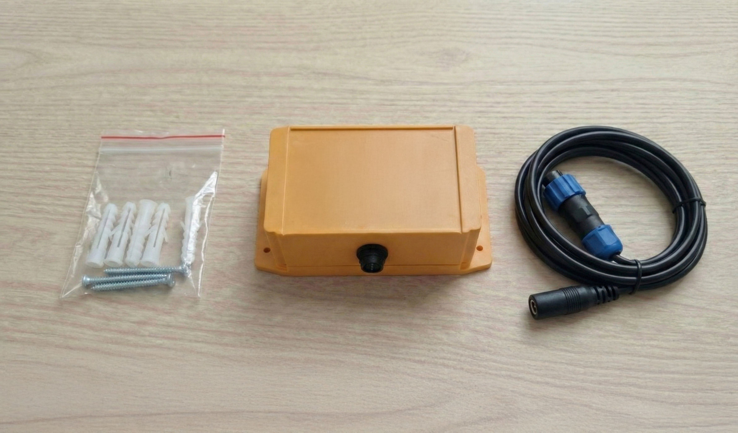
2. IP67 weatherproof enclosure (optional)
If ordered with enclosure:
- IP67-rated weatherproof housing
- Pre-drilled cable entry points
- Weatherproof cable glands
- Desiccant pack for moisture control
Note: Enclosure color may vary from shown.
3. LTE antenna
Internal antenna for cellular connectivity (built into enclosure).
4. Power cable
SP13 male to female DC barrel connector cable:
- Connects to female WEIPU SP13 port on enclosure
- Compatible with solar panels (6-10V input)
- Compatible with external power supplies
5. Quick start guide
Printed card with basic setup instructions and QR code for online documentation.
6. Mounting hardware
- Mounting bracket
- Stainless steel screws and anchors
- Cable ties for antenna routing
Sensor unit details
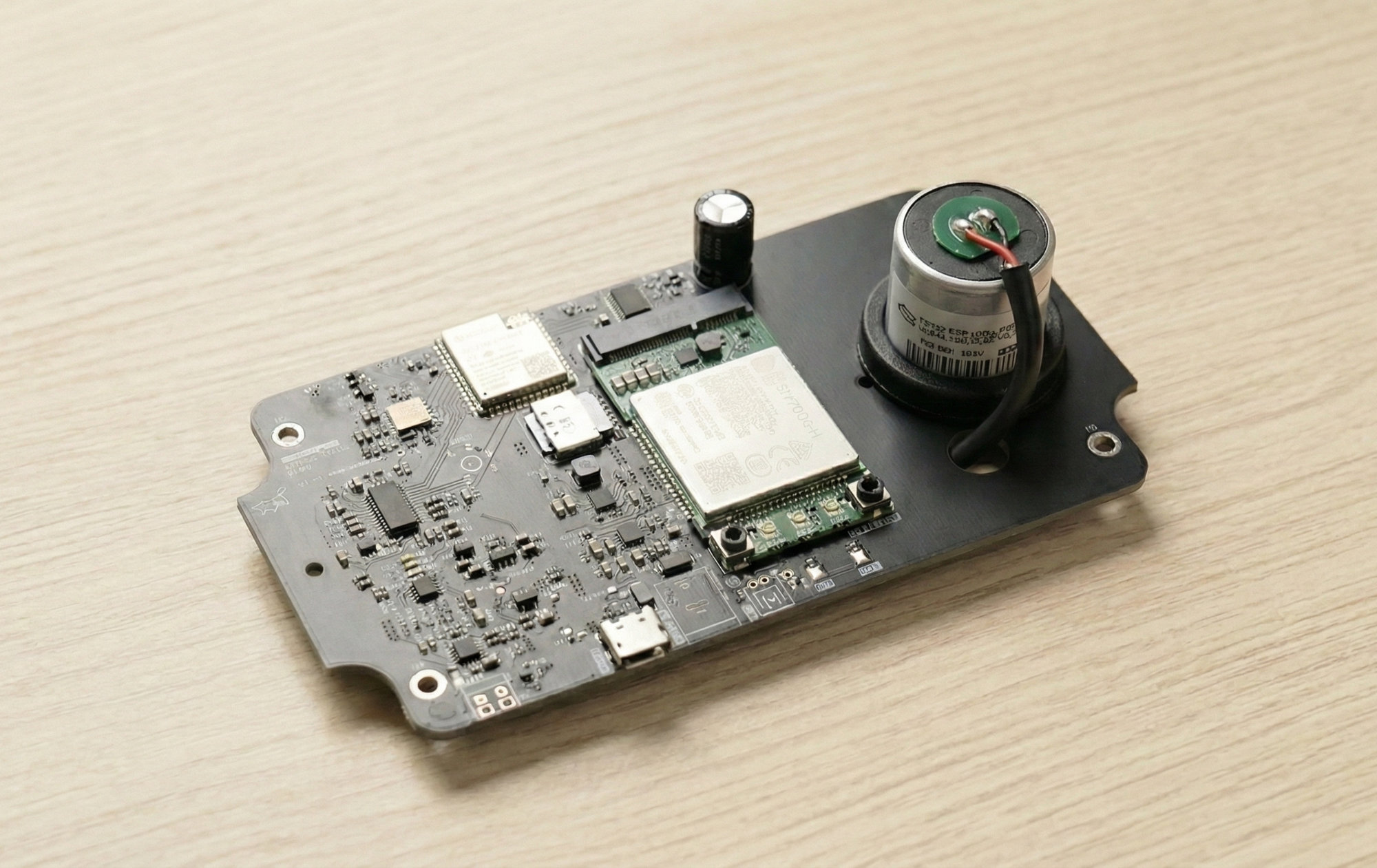
PCB layout
The Grillo Pulse PCB includes:
| Component | Description |
|---|---|
| Geophone | 4.5Hz vertical sensor with 32-bit ADC |
| MEMS accelerometer | Ultra-low noise triaxial with 20-bit ADC |
| LTE modem | Cat-4 with 2G/3G/4G fallback |
| WiFi module | 802.11 b/g/n (2.4 GHz) |
| Microcontroller | Dual-core processor |
External connections
- Power input - 6-10V DC (solar/battery compatible)
- LTE antenna port - SMA connector for cellular antenna
- USB port - For power and firmware updates
- Status LEDs - On-board indicators (not visible through standard enclosure)
The status LEDs are located on the PCB and are not visible through the standard IP67 enclosure. They are primarily for debugging and testing before final assembly. For deployed sensors, use the Grillo Cloud dashboard to monitor sensor status and connectivity. If you need visible LED indicators, consider using a custom enclosure with a transparent lid.
Internal components
- SIM slot - Nano SIM card holder
- Reset button - For factory reset
- Debug port - USB serial data output
Labels and identifiers
- Device ID - Unique identifier on PCB label
- QR code - For quick provisioning
- MAC address - For network identification
Verify your package
Before beginning setup, verify all components are present and undamaged:
- Sensor PCB is intact with no visible damage
- Enclosure is intact (if ordered)
- LTE antenna is included
- Power cable is present
- Quick start guide is present
- Mounting hardware is complete
If any components are missing or damaged, contact Grillo support before proceeding with installation.
Device ID location
You'll need your sensor's Device ID during provisioning. It can be found:
- On the PCB - Printed label on the circuit board
- QR code - Scannable code on the PCB
- Packaging - Label on the outer box
Take a photo of the Device ID and QR code before installing the PCB in the enclosure. You'll need it when adding the sensor to your Grillo Cloud dashboard.
SIM card information
The Grillo Pulse uses a Nano SIM card for cellular connectivity.
SIM card requirements
| Requirement | Specification |
|---|---|
| SIM size | Nano SIM |
| Network technology | LTE Cat-4 (2G/3G/4G fallback supported) |
| Data plan | Active data plan required |
| Recommended | M2M/IoT data plans |
Pre-installed SIM
Some Pulse units ship with a pre-installed, pre-activated SIM card:
- Ready to use immediately
- Data plan may be included for initial period
- Check your order details for specifics
User-provided SIM
If providing your own SIM card:
- Must be Nano SIM size
- LTE Cat-4 compatible (most modern SIMs work)
- Active data plan required
- See SIM card setup guide
Next steps
Once you've verified all components: